Select your language

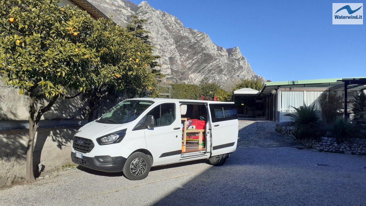
Anyone who loves outdoor life and sports dreams of having a small  camper, or a van transformed in a camper, for the freedom that traveling with such a vehicle gives. In this article, I will tell you about my experience in converting a Ford Transit Custom into a kind of camper.


Converting a van into a camper (Ford Transit Custom)


Let me start by saying that camperizing a van is not a walk in the park. It is not an impossible job, even if it requires a certain amount of manual skill, but it requires many hours of work, and a lot of mental energy in the planning. You will find yourself thinking about how to solve a problem, perhaps when waking up at night (and, personally, some of the best ideas have come to mind at night). Obviously, then, once the work is done, you could be very satisfied with what you have done, in addition to finally being able to enjoy your van for wonderful adventures.

In this article, I will tell you about my experience on the various topics related to camperization, stating that, having no previous experience, I searched online, watched many videos on YouTube, asked several friends who had already had experience, and I also made some mistakes, obviously. I must also say that what was proposed online and on YouTube was not always convincing for me, and in some cases I made different choices. Finally, it must be said that wanting to cram sports equipment into the cargo area of ​​my Transit, and wanting to maintain reasonably large spaces (so as not to obtain a claustrophobic result), I did not carry out a massive camperization (for example, I never thought of beading the interior). Having said this, I will proceed in order to deal with the various topics, and to tell you what I did.

Topics covered: Insulationfloor construction, the windwos installationthe windwos installationmaking the bedelectrical systemair heating, plumbing systemthe kitchen cabinet.


By clicking here , you will be redirected to the page with the lists of most of the products I recommend or use for camperizing your van (I didn't buy everything on Amazon).

The products are divided into the following categories: Gas , Electricity , Plumbing , Insulation , Coatings/Furniture/Tools

In the coming months, I will be doing some more small van remodeling work. For example, I will have to figure out how to store all the kitchen and bathroom products and utensils, as well as clothing, in the cargo area. I will update the article to explain any additional solutions and ideas I find. Stay tuned and come back to consult this valuable guide.


Insulation


If, like me, you start with a commercial vehicle, the first thing to think about is the insulation of the cargo area of ​​the vehicle, which will become your accommodation. There are various alternatives.

I proceeded as follows. As for the floor, I considered that the sheet metal of the vehicle, in this part of the vehicle, is not in direct contact with the outside (but protected by the underbody covering of the van). I also considered that on top of the insulation I then laid a 12 mm marine plywood floor. Therefore, I created an insulation of intermediate thickness.

Specifically, I positioned 2 cm XPS (Expanded Polystyrene) panels, which are typically used in construction. I purchased them from Leroy Merlin (but you can also find them on Amazon). They are 1200 x 600 mm panels (I needed 6 for the entire floor). To anchor them a little to the body of the vehicle, I used adhesive polyurethane foam. This is not a strictly necessary step, but it is useful when assembling or disassembling the floor, to keep the underlying panels in place. I placed four whole panels, centrally; and two more, after cutting them lengthwise in half, I shaped them to match the side profile of the  van 's loading platform , in correspondence with the wheel arches. For the cutting profile, I first took all the measurements, and drew the shape on the panels, helping myself with a sheet of paper to draw the template of the profile with a pencil to then transfer it to the side panels. To cut out the shape, I used a sharp cutter. Keep in mind that you can, however, try to lay the panels on the floor of the van, and make adjustment cuts with the cutter, until you obtain a satisfactory result.

By laying the panels cut out in this way, and the central ones side by side, they are already quite "stuck together". The adhesive foam makes their arrangement even more stable. XPS, normally used as an underlay for insulating floors in buildings, has good resistance to trampling (but don't put your knee on it, or you'll leave a mark).


As for the side walls and roof of the van, I proceeded as follows.

I discarded the initial idea of ​​covering the walls and roof with XPS panels, both because they would have reduced the internal dimensions of the van's storage space a bit too much, and because it is not a very aesthetically pleasing solution. I would then have had to cover the XPS panels with other wooden panels, taking away more space.

As for the lower portion of the sides and rear doors of the cargo area of ​​the van, which were already almost completely equipped with original panels to protect against the transported load, I created the insulation with rock wool. I believe that this is a very valid solution, because it is easy to implement and very low cost. The 10 kg that I bought for 40 euros were more than enough for the entire lower portion of the cargo area of ​​the van. I glued a first part of the wool to the bodywork with adhesive polyurethane foam, and I easily fitted the remaining part by manually tearing off patches of the necessary size. Then, I reassembled the protective panels, which I previously painted with two coats of water-based enamel as a base, and two coats of solvent-based enamel, to make them waterproof. I had to make two missing panels myself, using mdf that I shaped as needed with a template made with a parcel sheet, on which I drew the profile to cut with a marker. Or, you can use a sheet of transparent plastic.


20241113 184928

20241113 112904


As for the upper part of the walls and rear doors, and for the ceiling, I finally decided to use Armaflex. This is a product that has a certain cost, but has a truly excellent quality, and with high thermal resistance. I took 5 m 2 of 9 mm thickness, enough for the walls and ceiling and also for the wheel arches. I am also very pleased with the final aesthetic finish, a sort of black velvet, similar to that of a car interior. Beforehand, I proceeded to soundproof the walls with a self-adhesive insulating mat in butyl aluminum.Car dealerships nearby

I will see, in the future, whether to also place an adhesive cork covering (more for aesthetic reasons) on the body pillars of the cargo area.


20241108 175034

20241116 193104

20241116 160403


Floor construction


Once the floor insulation was done, I moved on to making the plywood floor, since the  van I bought did not have one. Among the options offered by a plywood wholesaler in my area were the following choices that were particularly suitable for this purpose: 

1) Okoume marine plywood

2) Marine plywood Mahogany

3) Film-faced marine plywood (resin coated)

For the floor, you need to opt for marine plywood, that is, a multilayer of wood that is particularly suited to withstanding humid conditions, without absorbing too much water or humidity, and deforming. Typically, in commercial  vehicles , the third product listed above is chosen. But I wanted to obtain, as a final result, a sort of Parquet, with the wood grain visible. Therefore, I opted for the first solution. Mahogany is particularly expensive. I opted for a thickness of 12 mm, so as not to steal too much space in height in the van, and to not have a floor that is too heavy to manage. A 12 mm floor already has sufficient rigidity to support the weight of the objects and foot traffic.

I made the floor with a single shape, except for a rear addition, in correspondence with the doors (see photo). Take into account the dimensions of the cargo area (even in the upper part) when you have the rough floor cut to be shaped, to be able to transport it. I assure you that it is not a trivial problem!  

Then, also in this case, I shaped the panel laterally to adapt it to the profile of the cargo area of ​​the van, with a method similar to that of the XPS panels, which I also used to trace the shape to cut in the floor. Please note that when tracing the shape on the plywood floor, I kept a margin (undercut) of a few centimeters (from 1 to 5, depending on the points). In fact, the cargo area of ​​my Ford Transit is irregular, and is not the same width at the top and bottom (at the top, it is narrower). If I had traced a shape precise to the centimeter, then, once the cutting floor was inserted from behind into the cargo area, I would not have been able to lower it and lay it down, because it would have gotten stuck in the upper part of the narrower body. In this installation operation, it is good to be in 4 and to take the panel at the four corners to move it more easily and without causing damage.

After having cut the plywood properly, I gave it two coats of colorless nautical flatting, obtaining a very nice and waterproof reddish finish, with the wood exposed (see photo).

I then protected the edges of the floor, in correspondence with the side and rear doors, with U-shaped plastic profiles, similar in appearance to wood. Furthermore, to prevent sand or dirt from getting into the sides under the floor, I sealed the perimeter of the floor, that is, the space between it and the body, with adhesive tape, also similar in appearance to wood, almost 6 cm wide. 


20241107 161642

20241107 173506

20241112 195938 20241128 201731

20241115 181616


Windows installation


Having bought a commercial vehicle with closed walls, I had to plan for the installation of two windows on the side sliding doors. Watching some videos on YouTube, I was able to see that some people independently cut the bodywork and install and seal the windows. After all, to cut the bodywork you only need a drill for the initial hole, and a jigsaw for the actual cut. But having bought a vehicle in good condition, and being my first experience in this regard, I wanted to avoid making mistakes, and I relied on a workshop that deals with camperization. I bought non-original windows for the Ford Transit Custom (Carbest brand), but compatible, and with darkened glass. I must say that I was very satisfied with the final result. The camper center in Brescia that did the work worked in a very professional manner.


20241206 155737


Making the bed


To make the bed, I prepared a project in advance by sketching the structure on sheets of paper, both to foresee possible problems of construction and to define the quantity of wood needed. I also took some ideas from the Internet.

Like many others who have tried their hand at camperization, I designed and built a single bed, expandable to a double bed. For this purpose, I created a system with slats that fit together along the width like the teeth of a comb (see photo to understand). I wanted to create an easily removable, modular structure (divided in two along the length)

First I made the frame, and then I fixed the slats.

I used only planed fir wood, partly bought from Leroy Merlin, partly ordered on online wood seller. Fir is a light, sturdy and easy to work wood. I thought a lot about the size of the bed. In the end, I made a bed of 190 x 80 cm (which reaches 150 when expanded to double), with 50 cm high legs. The height of the legs is the best compromise I found between the need to store mainly windsurfing equipment under the bed and the liveability of the van, that is, the possibility of sitting on the bed without touching the ceiling of my Transit with my head (which is quite high). The width manages to exploit a good part of the width of the cargo area. The length takes into account the fact that I have a kitchen cabinet leaning against the dividing wall between the driver's cabin and the cargo area, and I didn't want it to rise too high over the bed, for practical reasons, given that I have the water tanks, the gas cylinder, and the inverter under the cabinet.

I divided the bed into two parts lengthwise, so that it can be removed easily. One piece is 120 cm long, with legs that are positioned on either side of the wheel arches; the other part is 70 cm long, and is the one that is normally located towards the divider between the cargo area and the cabin (and is the one on which the feet rest). But this modularity also allows me to invert the order (larger part placed near the divider), so that, by extending only the smaller part in length, I get a sort of L-shaped sofa, comfortable for eating around a table, or relaxing with several people.


20241211 153615

20241214 151312

20241107 173506

20241214 171223

20241214 171223


The legs and crosspieces have a section of 4.5 x 4.5 cm. The slats have dimensions of 15 mm x 80 cm x 10 cm (but the correct width, see later, was 9.5 cm, and so I had to rectify it). To join the legs to the longitudinal and lateral crosspieces of the bed frame I used steel corner plates fixed to the wood with screws, in addition to adding Millechiodi glue at the contact points of the wooden strips. The resulting structure seems sturdy and solid to me. This system was quite practical and fast, even if it still required a bit of manual skill. I only point out that the final tightening of the screws always moved the corner plate slightly, causing the edges of the joined strips not to line up perfectly. Maybe, I recommend at least getting some plates with an invitation for the screw head. Or, suggest other solutions in the comments.

Initially, I planned to place 17 slats, 10 cm wide, in total in the central portion of the two modules, plus 2 5 cm slats at the end of each module (in the main part and not in the extension, where I only placed the normal slats). But when it came to positioning them, before fixing them with screws to the longitudinal crosspieces, I realized that there wasn't room for all the slats, and in any case they would have had difficulty sliding between each other, fitting together like a comb. So I had the 10 cm ones trimmed to a width of 9.5 cm. Furthermore, in the smallest module, to avoid having slats too far apart under the mattress, in the main part and in the extension, I had to position the 5 cm slats as follows (see photo): one at one end of the main part, and the other at the end of the extension. In the middle, staggered, the other 6 9.5 cm slats were positioned. It would have been easier to plan a bed size of 180 cm or 200 cm. Or, I should have studied a different width for the slats. In any case, the solution adopted satisfies me.

For further details of the structure, I refer you to the photos below which show how it was made and how it works.

Finally, I painted everything with the same colorless nautical flatting, which gave the bed a beautiful, glossy, and waterproof finish.


20241211 174812


Electrical system


The calculations and explanations below may seem boring and complex. But it is worth losing your head a little, because with electricity and the risks associated with its use you do not joke! Otherwise, contact an electrician, or a competent friend.

As regards the electrical system , proceeding from the production to the final consumption of energy, I chose the following system scheme.

First of all, I installed two Eco Worthy 130 W 12 V flexible monocrystalline solar panels on the roof, with a thickness of only 2.4 mm (see recommended products on Amazon at the beginning and end of the article). The panels were glued to the back of the van roof with a special sealant, Sikaflex 522. In this regard, I would like to immediately say that Sikaflex is a fantastic and very effective glue. All you have to do is place the panel on the roof of the van covered in glue and it will grip almost immediately, with the possibility of moving it slightly for some small adjustments, in the minutes immediately following. Sikaflex, however, needs about 24 hours to dry completely. It is a glue designed to guarantee sealing and resistance to atmospheric agents for about 10 years. The stories you read online, of panels that flew off on the highway, are probably linked to the use of different and incorrect glues.

Before attaching the panels to the roof, it is good practice to place them on the roof, and arrange all the elements of the system in their place (perhaps, only temporarily fixing the cables with adhesive tape along the desired path), to notice any installation problems. Once you have done the test, and found that there are no problems, mark the position of the panels on the roof with a marker (just mark the 4 corners of each panel).

Then, draw a serpentine with the glue in the area where you will place the panel (see photo below), also drawing lines along the perimeter, especially along the windward side, where the air that gets underneath could have more leverage to lift it. Once each panel is placed, leave the vehicle parked in a sheltered place (better if at a temperature above 15 degrees to speed up the drying of the glue). I also put some Grey Tape (white in my case), along the windward edge of each panel, to prevent air from getting underneath and tending to lift it. However, keep in mind that a certain air circulation under the panel does not do any harm. In fact, the performance of the panels decreases as the temperature increases, and, therefore, it is good for some air to pass under them in the summer to cool them down. Some also suggest wetting them with water, when your vehicle is parked in the sun, always with the aim of cooling them down a bit.

I bundled the connector joints of my two roof panels with plastic zip ties and white self-amalgamating tape, and then secured them to the roof with Grey Tape.


20241208 190232

20241209 124422

20241208 195507


Downstream of the connections, the 6 mm 2 panel cables were passed through a passage, fortunately specially prepared for this purpose, present at the height of the headlights, in each rear edge of the Ford Transit Custom body, hidden behind the doors. The passage is already fairly protected by a raised profile from water infiltration (in any case, after passing the cables, I also applied some Grey Tape). The presence of this passage saved me from having to drill holes in the body, a non-trivial operation.

The panel cables, passed through a corrugated tube ceiling track, reach a charge regulator (supplied with the KIT I bought), and then arrive at the 140 Ah 12 V AGM battery, in my case, conveniently positioned in the driver's cabin, under the passenger seat (see recommended products on Amazon at the beginning and end of the article) .

For this last purpose, I decided to equip myself with a battery with a generous charge storage capacity, and therefore duration, to power some particularly energy-hungry appliances, first and foremost the hot water boiler that I decided to install (see below).

The battery, with adequately sized cables (I will mention the calculation shortly), is connected to a 2000W inverter, with a peak of 4000 W 12V 220V-230V Pure Wave DC AC (see recommended products on Amazon at the beginning and end of the article) . I wanted to install this inverter because the boiler requires a maximum power of 1200 W, and I would also like to occasionally use a heater with a power of 1000-2000 W, or a hair dryer with a power always around 2000 W. The hair dryer and heater will work for a few minutes (10-15 minutes max) over the course of a day. The boiler, to bring the water to the temperature necessary for the shower, must remain on at 1200 W for about 20 minutes.

I therefore calculated the charge consumed by the boiler during its operation to define the battery charge storage capacity.

The boiler consumes 1200 Watts (Joule/s) of energy, and as mentioned it must work for about 20 minutes. By multiplying the power by the time, you get the amount of energy consumed by the boiler in this period of time, therefore: 1200 J/sx 20 minutes x 60 s/min = 1440 KJ. The battery works at a voltage of 12 V, or 12 J/C, that is, each electric charge of 1 Coulomb contributes an energy of 12 Joules. Therefore, by dividing the amount of energy consumed by the boiler by the energy per unit of electric charge, you can calculate the amount of total electric charge consumed, that is, transferred from one pole to the other in the battery (which will then need to be recharged to restore its accumulation): 1440 Kilo Joules : 12 Joules/Coulomb = 120 x 10 3 Coulombs.

The battery charge storage capacity is measured in Ah. The Ampere (A) is the unit of measurement of the current intensity, or the flow of charges in the circuit in the unit of time. 1 A is equal to a flow of 1 Coulomb/s. Therefore, a current intensity of 1 A for 1 second is equal to 1 Coulomb. It follows that 120 x  10 3 Coulomb, or the charge consumed calculated above, corresponds to 120 x  10  A x s. An hour is equal to 3600 s, so dividing by this conversion factor, we ultimately obtain:  120 x  10  A xsx 1 h/3600 s = 33.3 Ah.  

Repeating the calculation, and considering devices that consume 2000 Watts, for similar times, the battery consumption reaches about 40 Ah. I therefore judged the 80 Ah battery I had available to be insufficient (on its own). In fact, this is the charge that the battery has when it is full, while when it is only partially charged, the battery may have a charge too close to that consumed by the electronic devices listed above, with the consequent possibility of almost completely exhausting the battery. Furthermore, it is also necessary to consider the intensity of the current that the battery can deliver (see below).

Therefore, I took the 140 Ah battery, which guarantees me an adequate reserve. I will see with experience whether to use both batteries to have even more charge reserve. Maybe, I will do it in case of trips to places with little solar radiation, and therefore little charging of the solar panels. In this case, the batteries will have to be connected in parallel, and not in series (otherwise, it would double the voltage!).

But be careful that the battery's capacity to deliver electrical charges with a certain current intensity also counts. So check this data plate carefully too. In my case, the 140 Ah battery is able to deliver an amperage of 860 A. In the following, we will see that the current intensity I requested is a maximum of 167 A.

Considering the power required by the electronic devices I use, I bought the inverter indicated above, capable of supplying such power with a good safety margin, and which can provide me with 220 V current, as required by the devices in question.

It is important to connect the battery and inverter with suitable cables, to avoid excessive energy dispersion and dangerous overheating of the cables, and to ensure that the final device receives the energy (or rather the voltage, i.e. the energy per unit of charge) that it requires. In this regard, in fact, it is important to keep in mind that, since the circuit between the battery and the inverter is 12 V, i.e. low energy transported per unit of charge, the current intensity (i.e. the flow rate of charges) will be very high.

According to Ohm's law, the voltage drop, i.e. the loss of electrical energy during the transport of charges in the circuit is proportional to the current intensity, i.e. ΔV = Ri, with R representing the electrical resistance which is measured in Ohm (Volts/Ampere), i.e. the coefficient of proportionality between the two quantities. R in turn, considering the overall circuit, is equal to

where  R  is the resistance,  L  is the length of the circuit cable,  A  is the cross-sectional area of ​​the circuit, and ρ is the specific resistance or electrical resistivity, in practice the resistance per unit of length and per unit of area. It is typical of the material the cable is made of and varies with the temperature. In the case of copper, which is what the cables I use are made of, the resistivity at 20°C is equal to 1.68 x 10 -8 Ohm xm 2 /m .

To reduce the overall resistance of the circuit, it is therefore advisable not to provide cables that are too long and to adequately increase the section. Keeping the cables as short as possible in the connection between the battery and the inverter is also an economic issue, because electrical cables with a generous section have a significant cost!!!

In concrete terms, I planned to place the battery 1.5 meters of wire from the inverter. Note that the total length of the circuit is the sum of the cable for the positive pole (the red one) and the one for the negative pole (black). So, in my case, the total length of the circuit is 3 meters.

Generally, it is recommended to keep the voltage drop (i.e. the energy loss per unit of charge) within 3% to avoid too much dispersion and overheating, and to actually get almost 12 V to the final device (the inverter in my case). So, considering the voltage guaranteed by the battery, I will have 12 V x 0.03 = 0.36 V of admissible voltage drop.

From Ohm's law, we can deduce that R =  ΔV/i. Considering an absorbed power of 2000 W (that guaranteed by the inverter, and absorbed by the most energy-hungry devices), the current intensity flowing in the cables is approximately 167 A. Ultimately, therefore, to contain the voltage drop to 0.36 V, with a similar current intensity, R must not exceed 0.0022 Ohm (V/A). 

From the formula that links resistance and resistivity indicated above, we obtain:

Cable area =   1.68 x 10 -8 Ohm xm 2 /m x 3 meters / (0.0022 Ohm) = 2.3 x 10 -5 m 2 . Since, 1 m 2 = 10 6 mm 2 , the required cable section is 23  mm 2. In practice, you then evaluate what is available on the market. To have an additional safety margin, I took two pieces of cable (black and red) of 35  mm 2 !


20250111 144309


Finally, I would like to add a piece of advice given to me by an engineer friend on the overall circuit:

Pay attention to another factor:

The charge controller that charges the battery from the solar panels would be in parallel between the battery itself and the inverter.

If the inverter is off there is no problem: the regulator slowly charges the battery.

But when you turn on the inverter, it requires a high current.

Check what happens to the regulator if too much current is requested, i.e. if it has any protection systems.

The current would be given by the battery but in this case the regulator would see its output as if it were shorted; therefore, it must be understood if it supports it, otherwise you will have to put a manual cut-off.

In light of this advice, I checked to see if the charge controller had protection against excessive amperage. My regulator does have such protection. However, it may be useful to section the circuit by installing a cut-off button after the charge controller, and before the battery.

Finally, I would like to point out that I installed two 12v and USB sockets on the right side of the van , in the center and on the back, to connect the fridge, cell phones, or external shower. I recessed these two sockets in two small boxes made by me in 10mm thick composite fiber (excellent material, easy to work with, and waterproof), with simple joints with screws. I then covered the boxes with adhesive paper in the same color as the protective internal panels of the bodywork, and then fixed them to the wheel arches and to the protective panel with double-sided tape with good hold (I am refractory and drilling the bodywork of the van ...).


20250108 183130


Air heating


As for heating the cargo area of ​​the van, at the moment I have not foreseen solutions such as Webasto, or other diesel heating systems. There are several on the market, even at low costs. But they require drilling holes in the bodywork to create the air intakes and the exhaust fumes. Furthermore, unless you make a connection to the vehicle's fuel tank (an operation to be carried out by expert personnel), it is necessary to provide at least one canister for diesel, and remember to check its level.

I made other choices. Since the cargo area of ​​the van has a volume of only 6 m 3 , it is quite simple to heat such a small space. It is clear that effective insulation is then needed to keep the heat inside. Furthermore, as mentioned, I equipped myself with a fairly large battery and an inverter capable of supplying up to 2000 W, and the electricity is produced for free by solar panels. Finally, I do not plan to go to the mountains with the van in the winter, but to have to deal with temperatures of just above 0 °C at most.

For these reasons, at the moment, when I need it, I carry a heater, that is, an electric fan heater that absorbs a power of about 1000 watts, and with which I quickly heat the interior of the van. Obviously, I only keep it on for a few minutes at most, so as not to drain the battery too much.


Plumbing system


After all that, could I do without running water (and hot water too) in my van? No.

In short, my plumbing diagram is as follows.

I have equipped myself with two 30-liter rectangular plastic tanks, with a small cap; one is for clear water, the other for dark water. The tanks are positioned under the kitchen cabinet (under the sink, to be precise), anchored to one of the hooks in the cargo area, using a tie rod.

I didn't need to get the more expensive wide-mouthed tanks, because I draw the clean water with a self-priming suction pump, with a 3/8" (9.5 mm) hose, connected to a rubber hose that goes into the pump, and I drain the water into the wastewater tank with a 1" (2.5 cm) corrugated hose that originates from the sink. In fact, I already had a wide-mouthed tank, which I will use with the 12V shower, for outdoor, summer showers. The shower has a pump that does not fit through the narrow neck of the normal tanks.

The pump I bought (see my recommended products list on Amazon) is able to deliver 4.3 l/minute, at 2.4 bar of pressure (about 24 meters of water column). The absorption, doing the necessary calculations, is therefore about 20 Watts. It works with 12 V current and is self-priming, that is, it is equipped with a pressure switch that starts the pump when I open the tap, or the electric water heater empties (see later), and stops it when I close the tap, and the boiler is full. I also provided a switch to disconnect it from the battery when I don't need it (as recommended in the product manual).

The pump delivery line is always made of 3/8 inch rubber (PVC) tube, for the first few centimeters, which I then connect with the necessary fittings to the flexible pipes of the hydraulic system. Long rubber tubes have been uncomfortable to manage, in my experience. In fact, unless you find them anti-torsion, they tend to remain curved and are uncomfortable (especially the suction one that you will not be able to adequately fish from the bottom of the tank).

A Y diverter is used to divide the water from the pump between the hose that brings cold water to the tap, and the one that feeds the water heater. From the water heater, the hot water then reaches the mixer tap that I installed on the kitchen cabinet top. The tap is equipped with a pull-out shower, with the option of also having a normal jet. The shower is convenient both for rinsing the sink and for taking a shower outside (1.5 m long hose), or inside the van (in this last regard, I am still studying the issue and I have to try out some ideas that I have in mind). I recommend carefully sealing the connections made to avoid problematic leaks along the circuit. In addition to the classic Teflon and hemp, there are single-component sealing products with PTFE additives, also suitable for gas pipe connections (see list of recommended products on Amazon).

The tap drains into a stainless steel sink measuring 355 x 260 x 150 mm, which I have built into the kitchen unit top (right side). There are also plastic sinks (trays) on the market, which can be used to rinse food, and equipped with a cap, which can be flattened and transformed into a cutting board; they can also be built into a wooden top. I wanted to opt for something more robust and long-lasting. A drain connects the sink drain to the corrugated pipe that conveys the dirty water into the grey water tank.

Among other things, I thought about how to have hot water in the van, since being able to rinse myself with hot water, even in winter, in places with outside temperatures that are not too low, but not comfortable either, is essential for me.

A first alternative is to buy a small portable LPG water heater. Cost around 190 euros, plus the cost of the cylinder. Obviously, during its operation it would have to be hung outside to avoid the formation of carbon monoxide (unless you study an air intake and exhaust directly with the outside), and it would also involve placing a LPG cylinder in the van compartment, which takes up a certain amount of space.
In addition, you would have to plan all the connection pipes around. The advantages would consist in the availability of hot water almost immediately, and in the fact of not consuming electricity, which is not always available.

Otherwise, you should opt for an electric water heater, quite small, but not tiny, which has the advantage of being able to work indoors, which costs about 80/100 euros, which does not require an additional cylinder, but unfortunately has the disadvantage of working with 220 V current and absorbing 1200-1500 W, which is not a small amount. You should therefore also install a suitable and reliable inverter, which costs about 190 euros, considering the power required.
As described in the paragraph on the electrical system , in the end I opted for the installation of the electric water heater.

In the future, I will see if I can install a plate heat exchanger to integrate the system and recover heat from the hot water in the engine, obviously not to use it directly, but to heat the water in an independent circuit that feeds the van's sanitary plumbing system. The idea is very interesting but it is not immediately feasible, because it involves the difficulty of modifying the vehicle's engine cooling hydraulic system, diverting it upstream of the radiator, and above all the difficulty of creating a hydraulic circuit to bring the heated water from the engine compartment to the van's cargo area. If you have any ideas and suggestions on this matter, write them in the comments.


The kitchen cabinet


The kitchen cabinet was "the mother of all battles".... I had to study the project for a long time to establish all my needs, define all the measurements, and even then it wasn't enough; I had to make some changes during the work. It was also the only phase of the work in which I injured myself (a slight strain to one leg while moving the cabinet)!

Anyway, getting to the point, I designed a 160 x 40 cm plan, in 12 mm Okoumè marine plywood (I used a scrap left over from the floor) where:

- built-in stainless steel sink (35 x 26 x 15 cm), with attached tap with shower head

- place a three-burner camping stove powered by a 2kg butane cylinder

- hang the inverter to have the current at 220, and the charge regulators of the solar panels

- fix the electric boiler (to the vertical wall, joined to the top of the furniture)

To make the legs of this top, I used sturdy planed fir strips with a section of 4.5 x 4.5 cm (like those used for the bed). I planned for the top to be 90 cm high so as to have approximately 50 cm between the top and the ceiling of the van . There are 6 legs in total, 4 at the lateral ends and one in the center, plus one 30 cm away from the rear left lateral one, always along the rear edge of the top (see photo below). These two nearby legs are actually 135 cm high, because I fixed the water heater to them. I inserted the dowels in a sturdy horizontal strip that joins the legs in question at the top. All the legs were joined at the bottom by horizontal reinforcement strips. I am thinking about some other modifications, to make the structure even more solid, but also to create an effective support where I can best anchor the pump and the hydraulic system fittings.

Finally, I fixed a panel to the rear edge of the floor, also in marine plywood (another leftover from the floor), joined vertically to the floor by sturdy steel plates. The panel serves as a protection for the partition between the cargo area and the driver's cabin of the panel, to avoid splashes due to cooking food, or from the sink.

I painted the cabinet with the same nautical flatting used for the floor, with the same pleasant aesthetic (and protective) result obtained for the van floor.

I placed two steel hooks at the top of the rear legs of the shelf, so that it can be effectively anchored to the hooks in the cargo area of ​​the van, to avoid dangerous movements or oscillations of the furniture when the vehicle is in motion.

When I put the cabinet in the van I unfortunately found that the measurements of the vertical panel did not take into account the upward taper of the sides and doors of the van, and so I had to make some shaping cuts to adjust the shape of the panel.


20250104 184455

20250106 125223

20250111 144309


The sink installation was not very easy. I wanted to make a precise installation to avoid movements of the sink, but I had to, again, cut the installation several times to correct the initially planned measurements. I recommend trusting the measurements suggested by the sink manufacturer..... I am considering whether, in addition to the silicone on the edge of the sink, used to ensure water tightness, to use a glue product on the edge of the sink in contact with the wood of the top, to make it more stable.

Next to the sink, as mentioned above, I installed a nice mixer tap, with a pull-out shower, connected to the plumbing pump.

In the center of the hob, I placed the three-burner stove (anchored to the hob with a strap or elastic rope, or clips).

A 1/2-inch hose connects it to the flame regulator, and then to the 2-kg cylinder, tied to the legs of the shelf under the water heater with a tie rod. It is useful to provide a hose long enough to carry the stove outside the van, whenever possible, to avoid impregnating what is in the van compartment with the smells of cooked food. If you cook inside, however, it is good to remember to ensure adequate ventilation, by opening the windows, also to avoid the formation of dangerous carbon monoxide.

Under the top of the furniture, in the center, I fixed the inverter, trying to make sure that those who sleep in the bed of the van do not hit it with their feet. The height of 90 cm of the top was also defined with this purpose, taking into account the height of the bed of 50 cm (+10 cm of mattress).

The water tanks are positioned on the right, under the sink. On the left, under the water heater, apart from the small gas cylinder, I did not want to place anything else, to leave room for the windsurfing equipment, stored under the bed (the bow of the boards reaches the cabin/cargo compartment divider). 

Well, I think I've given you a lot of ideas, and shared my experiences and possible pitfalls. Now all you have to do is get to work!

If you have any comments, ideas or suggestions, please write them in the appropriate section below (only for Waterwind Supporters).

Good work. Fabio


By clicking here , you will be redirected to the page with the lists of most of the products I recommend or use for camperizing your van (I didn't buy everything on Amazon).

The products are divided into the following categories: Gas , Electricity , Plumbing , Insulation , Coatings/Furniture/Tools


Without your Support, Waterwind wouldn't exist. Become our supporter!

If you want to advertise with us, read here, or contact us.

Collaborate with us. Read here!

Buy our Gadgets! Visit our YouTube channel!

No comments